- 您现在的位置:买卖IC网 > Sheet目录528 > TSL26711FN (AMS-TAOS USA Inc)IC PROXIMITY DETECTOR 6-DFN
TSL2671
DIGITAL PROXIMITY DETECTOR
TAOS118 ? JANUARY 2011
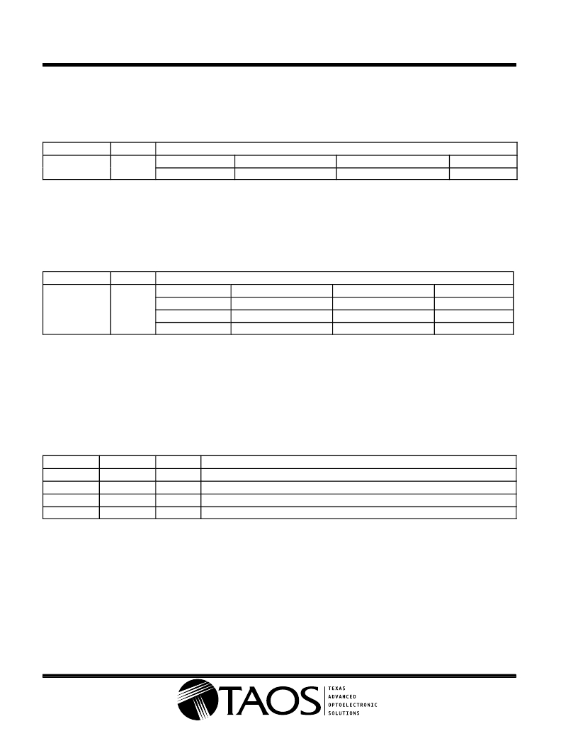
Proximity Time Control Register (0x02)
The proximity timing register controls the integration time of the proximity ADC in 2.72 ms increments. It is
recommended that this register be programmed to a value of 0xFF (1 integration cycle).
Table 4. Proximity Time Control Register
FIELD
BITS
DESCRIPTION
PTIME
7:0
VALUE
0xFF
INTEG_CYCLES
1
TIME
2.72 ms
MAX COUNT
1023
Wait Time Register (0x03)
Wait time is set 2.72 ms increments unless the WLONG bit is asserted, in which case the wait times are 12 ×
longer. WTIME is programmed as a 2’s complement number.
Table 5. Wait Time Register
FIELD
BITS
DESCRIPTION
WTIME
7:0
REGISTER VALUE
0xFF
0xB6
0x00
WAIT TIME
1
74
256
TIME (WLONG = 0)
2.72 ms
201 ms
696 ms
TIME (WLONG = 1)
0.032 sec
2.4 sec
8.3 sec
NOTE: The Wait Time register should be configured before PEN is asserted.
Proximity Interrupt Threshold Registers (0x08 ? 0x0B)
The proximity interrupt threshold registers provide the values to be used as the high and low trigger points for
the comparison function for interrupt generation. If the value generated by proximity channel crosses below the
lower threshold specified, or above the higher threshold, an interrupt is signaled to the host processor.
Table 6. Proximity Interrupt Threshold Register s
REGISTER
PILTL
PILTH
PIHTL
PIHTH
ADDRESS
0x08
0x09
0x0A
0x0B
BITS
7:0
7:0
7:0
7:0
Proximity low threshold lower byte
Proximity low threshold upper byte
Proximity high threshold lower byte
Proximity high threshold upper byte
DESCRIPTION
Copyright E 2011, TAOS Inc.
16
r
www.taosinc.com
r
The LUMENOLOGY r Company
发布紧急采购,3分钟左右您将得到回复。
相关PDF资料
TSOP57238TT1
IC IR RCVR MODULE 38KHZ
TSOP6238TT
IR RECEIVER 38KHZ 40M TSOP6238
TSTFT3.5I#
TOUCH PANEL 140X1.4.0 TFT
TSTFT5.7I#
TOUCH PANEL 132.5X104.7 TFT
TT8J21TR
MOSFET P-CH 20V 2.5A TSST8
TT8J2TR
MOSFET 2P-CH 30V 2.5A TSST8
TT8K2TR
MOSFET 2N-CH 30V 2.5A TSST8
TT8M2TR
MOSFET N/P-CH 30V 2.5A TSST8
相关代理商/技术参数
TSL26713FN
功能描述:近程传感器 Prox Det LTD I2C 6 Pin ODFN
RoHS:否 制造商:Vishay Semiconductors 感应方式:Optical 感应距离:1 mm to 200 mm 电源电压:2.5 V to 3.6 V 安装风格:SMD/SMT 输出配置:Digital 最大工作温度:+ 85 C 最小工作温度:- 25 C 系列:VCNL3020
TSL2672
制造商:AMSCO 制造商全称:austriamicrosystems AG 功能描述:DIGITAL PROXIMITY DETECTOR
TSL26721FN
制造商:TAOS Inc 功能描述:IC PROXIMITY DETECTOR 6-DFN
TSL26723FN
制造商:TAOS Inc 功能描述:IC PROXIMITY DETECTOR 6-DFN
TSL267-LF
功能描述:光频率和光电压 Light to Voltage Precision NIR RoHS:否 制造商:ams 峰值波长:1000 nm 工作电源电压:5 V 最大工作温度:+ 85 C 最小工作温度:- 25 C 安装风格: 封装 / 箱体:
TSL267SM-LF
功能描述:光频率和光电压 Light to Voltage Converter RoHS:否 制造商:ams 峰值波长:1000 nm 工作电源电压:5 V 最大工作温度:+ 85 C 最小工作温度:- 25 C 安装风格: 封装 / 箱体:
TSL2771
制造商:AMSCO 制造商全称:austriamicrosystems AG 功能描述:LIGHT-TO-DIGITAL CONVERTER with PROXIMITY SENSING
TSL2771 EVM
功能描述:光学传感器开发工具 Evaluation Module TSL2771x RoHS:否 制造商:ams 工具用于评估: 接口类型: 最大工作温度:
